You will find below all the technical constraints allowing you to prepare your files for custom cutting:
- Preparing a vector file for cutting
- Technical constraints for milling cutting (thick wood, expanded PVC, alu-dibond...)
- Technical constraints for laser cutting (thin wood, PMMA...)
Preparing a vector file for cutting
What is a vector file?
Vector image:
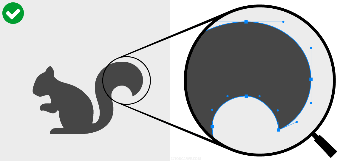
Visual defined by vectors (traced with points and tangents).
Raster image (or "bitmap"):
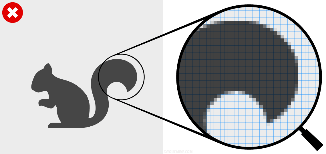
Visual defined by pixels (unsuitable for machining).
Accepted vector file formats:
Extensions PDF, SVG, AI, EPS (avoid if possible CDR, DXF, or DWG formats which are frequently subject to compatibility issues on our software)
Scale:
The vector file should be at a scale of 1 or 1/10.
Color mode:
RGB or CMYK, it doesn't matter.
Appearance and quality of the outlines:
Shapes must be defined by closed outlines, with a solid background color, without a contour attribute (neither color nor thickness).
How to properly prepare your vector file?
All the following tips will allow you to correctly size your visual for manufacturing and prepare vector outlines that comply with machining constraints.
Vectorize outlines
All outlines with a thickness must be vectorized (and merged, if necessary).
Desired result:
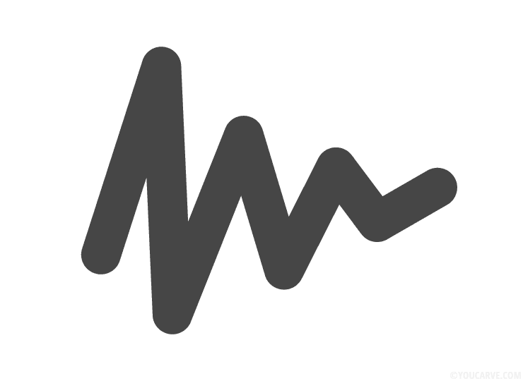
Do not do:
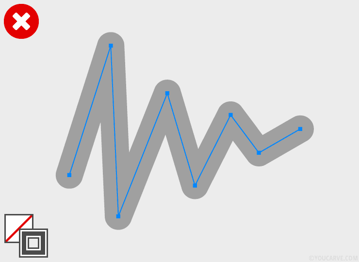
The visual is made with an outline without a fill and a thickness on the contour.
Do:
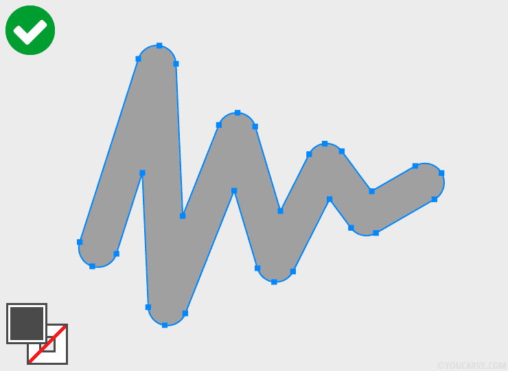
The outline has been vectorized: we obtain an outline with a fill, and a contour without thickness.
Merge shapes
Overlapping or adjacent shapes must be merged.
Desired result:

Do not do:
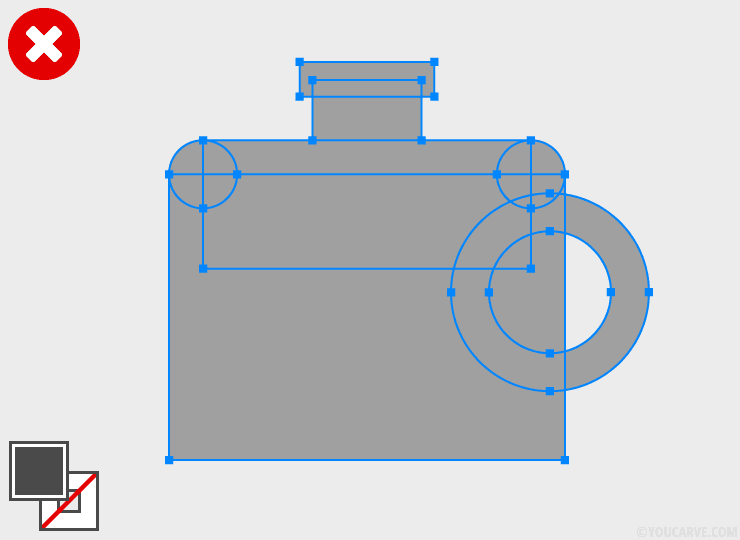
The visual is made with several overlapping or adjacent shapes (which leads to numerous intersections of outlines).
Do:
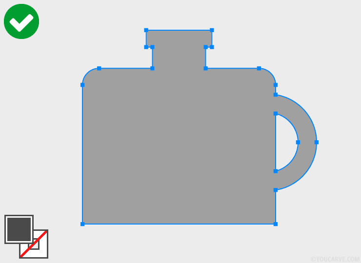
The shapes have been merged.
Vectorize texts
All texts created from a font must be vectorized (and merged, if necessary).
Desired result:

Do not do:
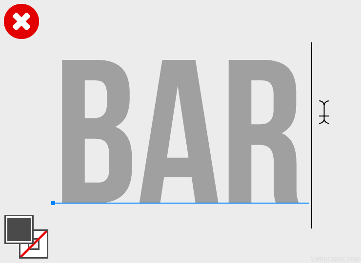
The text is in editable format.
Do:
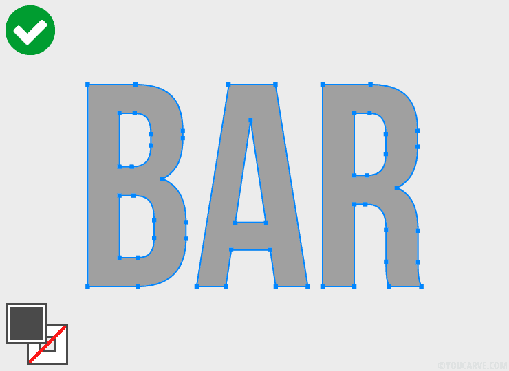
The text has been vectorized.
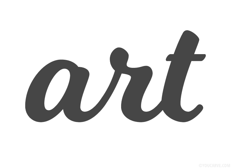
Desired result:
Do not do:
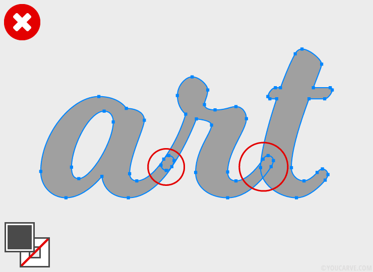
When vectorizing a script/calligraphic font (where letters are linked together), each letter is vectorized independently, which creates overlapping shapes.
Do:
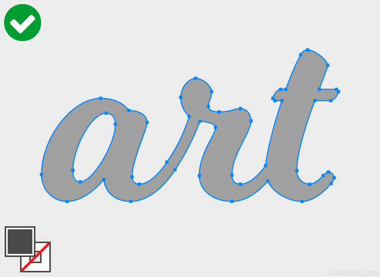
After vectorization of a script/calligraphic font, it is necessary to merge all the letters.
Technical constraints for milling cutting
Dimensions of the largest elements
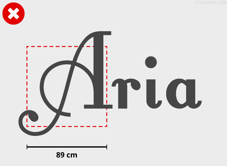
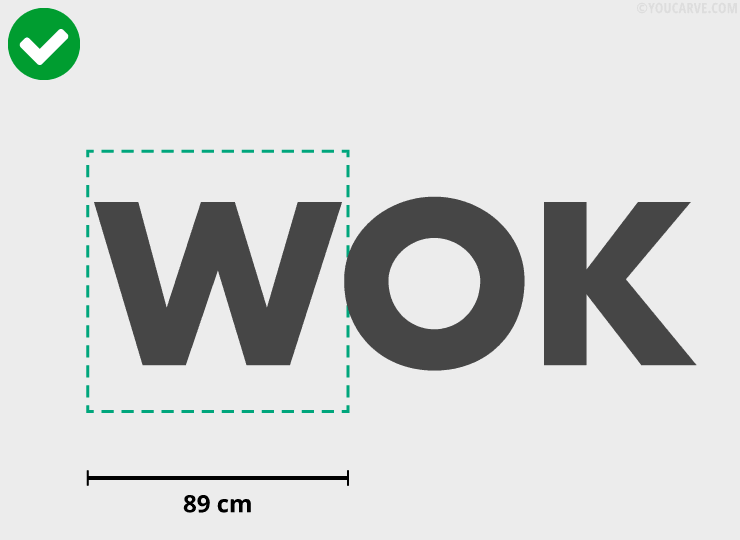
The largest independent elements (in other words, single pieces) must be able to fit within an 89 cm x 89 cm square.
In the case of a larger shape, we invite you to divide the piece into two (or more) edge-to-edge parts in such a way that the above constraint is ultimately respected.
Dimensions of the smallest elements
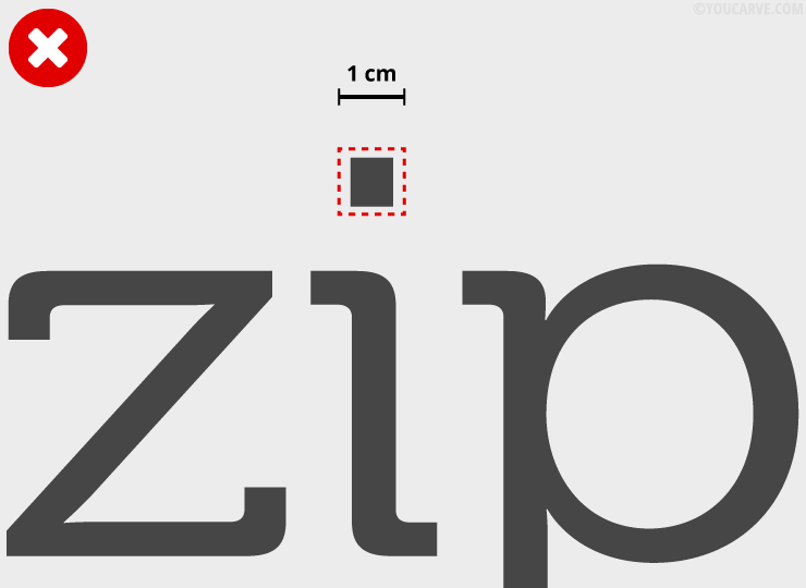
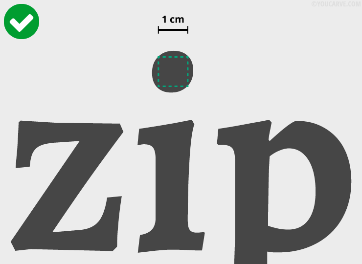
The smallest independent elements (distinct shapes) must have a surface area greater than 1 cm².
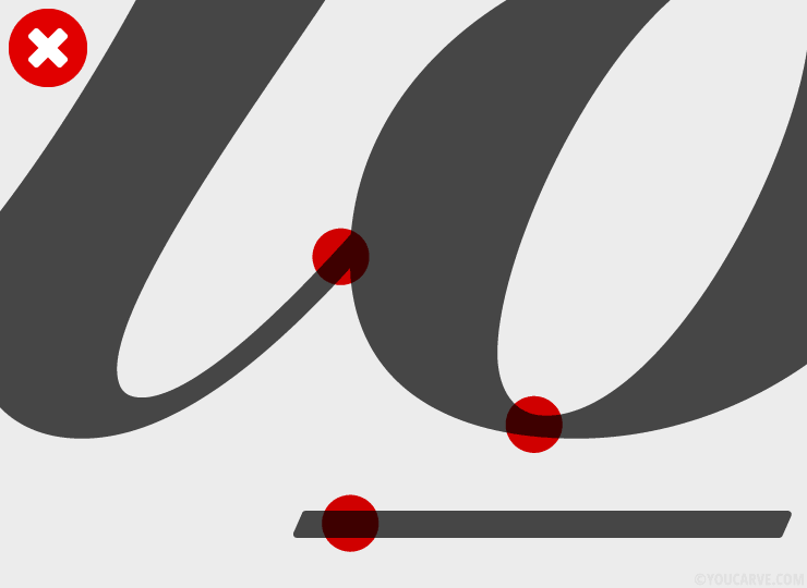
Finest solid parts
The width of the finest solid parts must be greater than:
• 4 mm minimum (6 mm recommended) for materials up to 10 mm thick
• 8 mm minimum (10 mm recommended) for materials over 10 mm thick.
Below these values, the solid parts are too fragile and risk breaking during manufacturing or transport.

Protruding parts
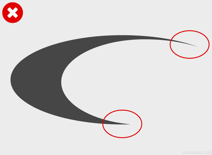
The protruding parts of the visual should not have a too fine and tapered point (leading to fragility and risk of breakage). If this is the case, we recommend correcting the visual, either by applying a rounding to the points, or by sufficiently thickening the shape.

Hollowed or recessed areas
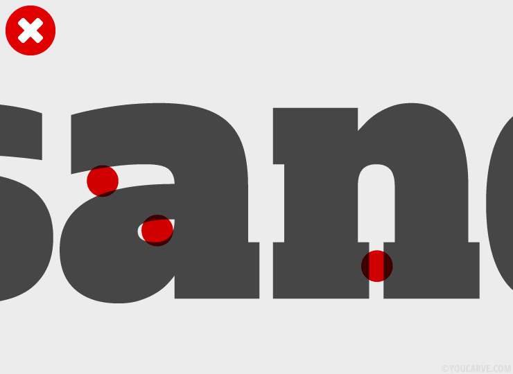
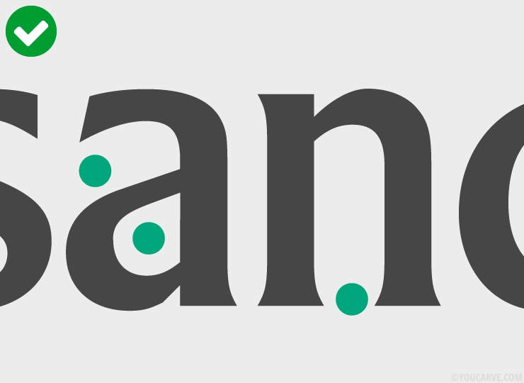
The hollowed or recessed areas of the same element must be large enough to allow the diameter of the milling cutter to pass through, otherwise they cannot be machined.
• Diam. 3 mm for materials from 3 to 10 mm thick
• Diam. 4 mm for materials from 11 to 20 mm thick
• Diam. 6 mm for materials from 21 to 30 mm thick
This does not concern the distance between disjointed elements (example: two very close but distinct letters), which will be spaced during manufacturing.
Additional constraint for chamfers
To allow for the proper execution of chamfers, the width of the finest solid parts must be greater than 5 mm (6 mm recommended).
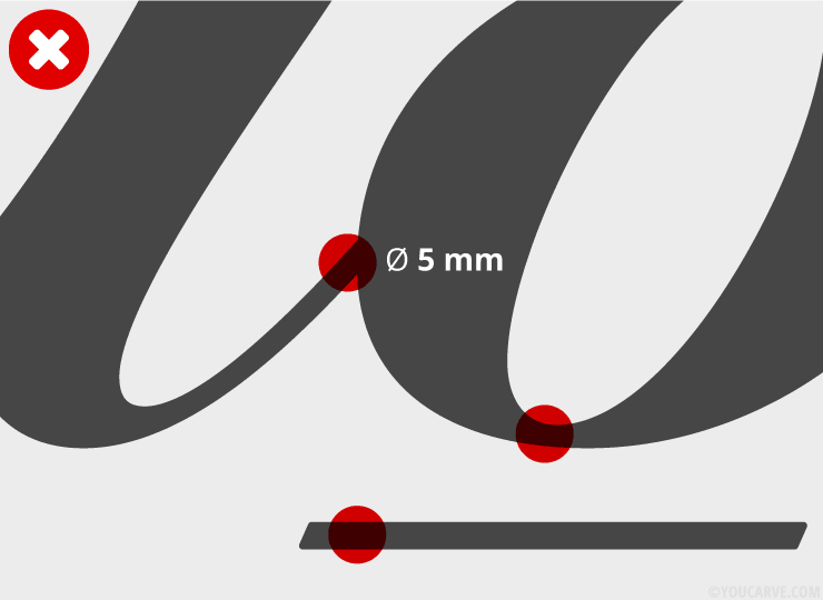
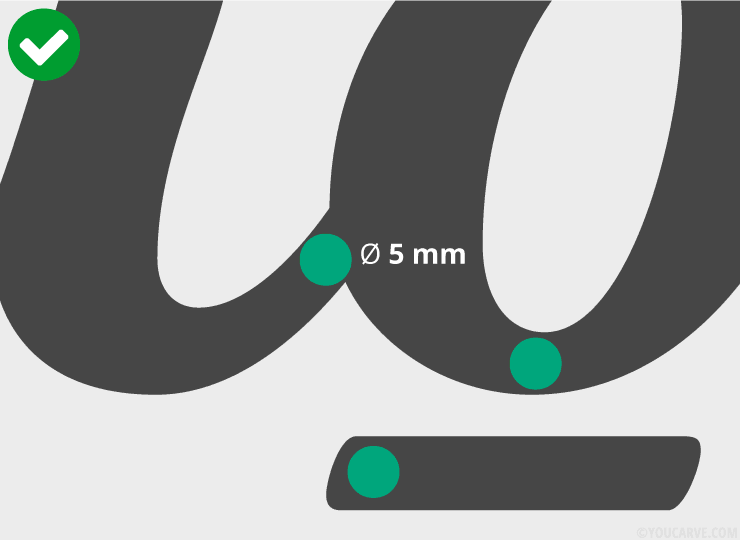
Additional constraint for spacers
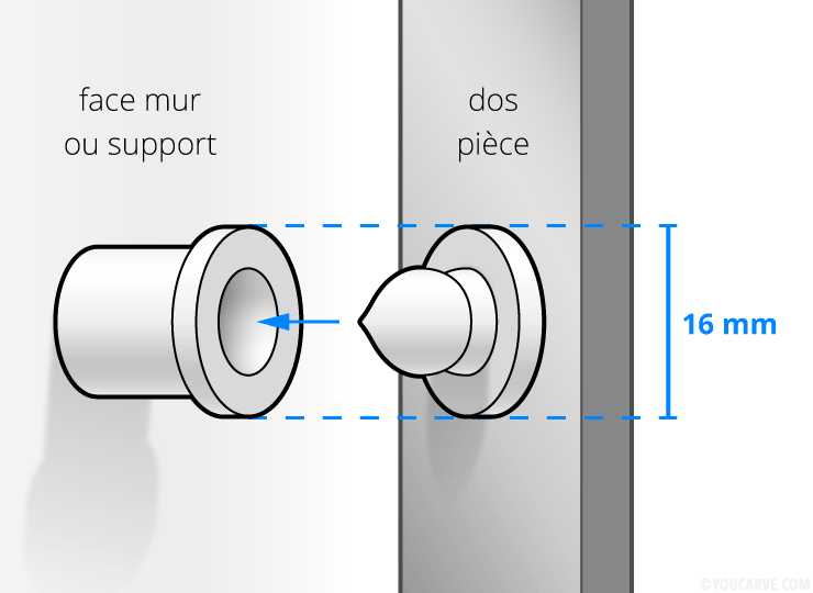
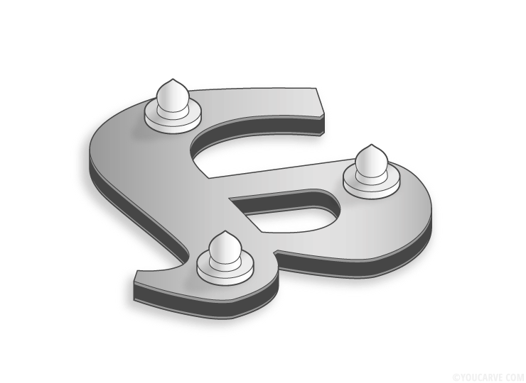
The clip-on spacer is a mechanical fastening made by fitting a tenon (male part) fixed to the back of the piece with a sleeve (female part) fixed to the support (wall or panel).
Each spacer represents a maximum footprint of diameter 16 mm.
You do not have to position the fixings, we will take care of that. However, you must ensure that the shape and dimensions of your visual will allow for the inclusion and distribution of a minimum number of spacer positions to ensure stable fixing of the pieces.
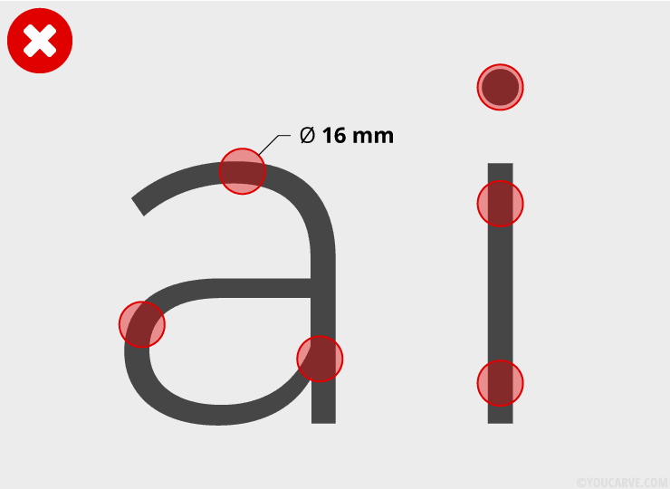
The fineness of the characters at this size does not allow for the positioning of spacer fixings. It is therefore necessary to either enlarge the visual or use bolder and therefore wider characters.
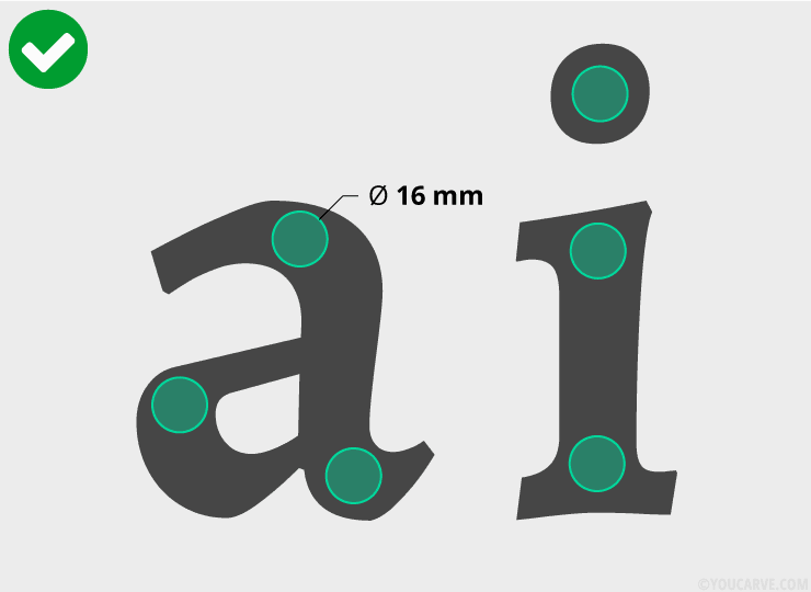
The visual at this size allows for the correct placement of spacer fixings.
Effect of the machining cutter diameter on internal angles:
In order not to have any surprises between the original visual and the manufactured part, it is important to understand the effect of the machining cutter diameter on the angles of the visual.
The external angles are perfectly respected and retain their vertices.
The internal angles undergo a slight rounding due to the diameter of the cutter: indeed, as it is round, it is not possible to obtain an internal angle finer than its diameter.
It is therefore not recommended to design a visual with too sharp internal angles, as they will be automatically rounded during machining. If your visual imperatively has internal angles, we recommend in this case, and if the material allows, to opt for the chamfering of the edges (optional) which will allow to restore a sharp finish to the internal points, and visually reduce this rounding effect.

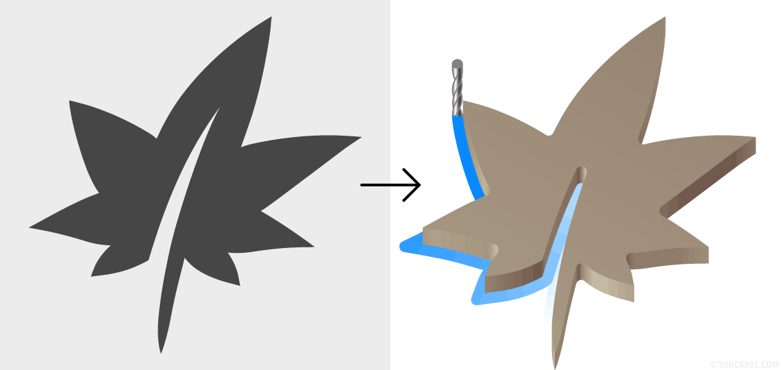
Here, for information, are the dimensions of cutters used depending on material thicknesses:
• diameter 3 mm (radius 1.5 mm) for materials from 3 to 10 mm thick
• diameter 4 mm (radius 2 mm) for materials from 11 to 20 mm thick
• diameter 6 mm (radius 3 mm) for materials from 21 to 30 mm thick
Technical constraints for laser cutting
Dimensions of the largest elements
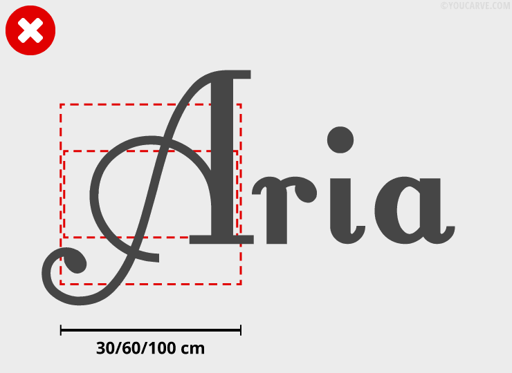
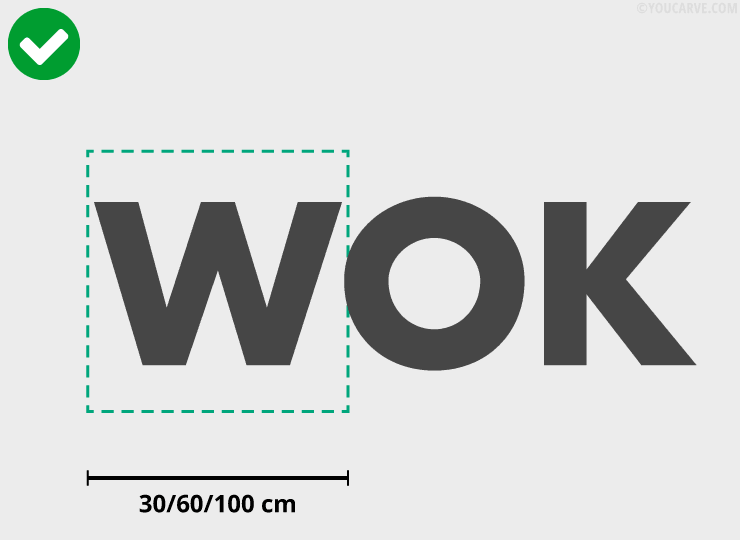
The largest independent elements (in other words, single pieces) must be able to fit within:
• a rectangle of 60 x 30 cm for solid wood thickness 5 mm (maple, oak, walnut)
• a square of 60 x 60 cm for PMMA (plexi) thickness 3 mm
• a rectangle of 100 x 60 cm for transparent PMMA (plexi) thickness 5 and 10 mm
In the case of a larger shape, we invite you to divide the piece into two (or more) edge-to-edge parts in such a way that the above constraint is ultimately respected.
Dimensions of the smallest elements
The smallest independent elements (distinct shapes) must have a surface area greater than 0.5 x 0.5 cm (0.25 cm²).


Finest solid parts
The width of the finest solid parts must be greater than 2 mm.
Below these values, the solid parts are too fragile and risk breaking during manufacturing or transport.


Protruding parts
The protruding parts of the visual should not have a too fine and tapered point (leading to fragility and risk of breakage). If this is the case, we recommend correcting the visual, either by applying a rounding to the points, or by sufficiently thickening the shape.


